
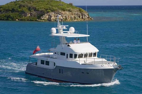
Nordhavn 64
After introducing the NORDHAVN 55, which closely followed the successful launching of the 43, 47 and 72, Pacific Asian Enterprises (P.A.E.) continues to strengthen its leadership position in long range, full-displacement passage makers with the NORDHAVN 64. The design incorporates the company’s styling and showcases its innovative approach to creating extra-spacious interior accommodations.
“The popularity of our 47, followed by the positive response we had to our 55, confirmed our belief that our customers want even more living space and more conveniences while they are cruising. The challenge is to provide these luxuries while maintaining the offshore capability of our boats,” said Jim Leishman, vice president of P.A.E. “Our 64 offers a remarkable amount of interior room, and she has the ability to cross any ocean. And because of modern systems she can be handled by an experienced couple, eliminating the need for paid crew.” Naval architect Jeff Leishman added, “I am very pleased with the outcome of the Nordhavn 64 design. The N64 draws on many of the elements of other Nordhavn designs, but it is also uniquely beautiful and elegant in its own special way. The N64 is nearly perfect.”
Structure
- Hull lamination schedule per construction plan. The area below water line to use “Isophthalic” gelcoat and vinylester resin for the first three (3) layers. The hull lamination will use “Combomat” in lieu of standard M+WR. Deck lamination schedule per construction plan. “Cymax” fiberglass will be used for all deck lamination.
- Standard gelcoat colors from Arocoat and CCP color chart. Gelcoat for deck and superstructure to be Ferro brand “Ultra” white
- Hull – Arocoat gray # 340
- Deck and deck house – Ferro “Ultra” white
- Boot top – Arocoat dark blue # 348
- Non-skid: Arocoat – light gray, to match CCP color chart # A110
- Exhaust stack/flybridge – Ferro “Ultra” White
Coring:
- Cabin side (vertical surfaces): Klegecell # R75 varying degrees of thickness
- Cabin top and deck (horizontal surfaces): Baltec or equivalent vertical end grain balsa, 1″ (2.54 cm) thick
- Hull: Solid series of laminates
Deck/hull joint:
- Between deck and hull flange: 3M 5200
- Inside of joint: Three (3) layers M. & W.R. (where accessible)
- Mechanical fastening: 3/8″ (9.5 mm) x 14 thru-bolt on 8″ (20.3 cm) centers
- Teak cap: Across stern only, varnished
Longitudinal Stringer:
- Hull: Seven (7) full length each port and starboard (total of 14), engine beds and floor stringers
- Interior floors: per std interior layout
- Ballast: Approx. 11,000 lbs (4990 kg) lead fixed per machinery layout drawing
- *Specifications subject to change without notice and at the discretion of designers and builders.
**Dimensions are subject to change with Buyer’s selected options and personal effects which may add to displacement and increase both draft and waterline length
Machinery
- Main Engine: John Deere 6135AFM75 424 hp (single) @ 1900 rpm, keel cooled with dry exhaust & 24 volt starting
- Gear Box: Twin Disc # 5114, with 3.43:1 electric shift, electric clutched ‘C’ PTO
- Engine Instrument Panels: Murphy PowerView, six (6) start/stop locations total
- Alternators: Two (2) 175 amp 24 volt DC belt driven
- Engine Controls: Twin Disc Electronic controls, six (6) stations: wheel house, fly bridge and aft deck, port and starboard Portuguese bridge and engine room
- Racor crank vent and air cleaner system
- Two (2) 4D batteries connected in series for 24 volt start
- Engine bed to have 3/16” (4.7 mm) stainless steel cap
- Stainless steel rail around engine
- Engine mounted on (4) vibration Isolator Polyflex mounts
- Fuel Filter: One (1) Racor 75-900MAC duplex with 2 micron filter elements in addition to secondary engine mounted filter
- Propeller: 4-Blade Hungshen “Silent” to be highest quality available 44” x 34.5” (111.76cm x 87.63 cm) – left hand rotation
- Propeller Shaft: A22HT 3-1/2″ (8.9 cm) diameter
- Taper details: Standard SAE
- Spurs line cutter on main engine shaft
- Stern tube: FRP
- Bearing: Rubber cutlass type at aft end
- Stuffing Box: Bronze-traditional
- Use “T” bolt clamps in lieu of hose clamps at the stuffing box
Keel Cooler
- Jacket water circuit: R.W. Fernstrum # D1281U-E1
- Engine cooling system to be filled with John Deere specified mixture of coolant/antifreeze
- Engine room floors: All engine room floors and structural members to be FRP with white gel coated surfaces
Noise Control
- Hull Damping – Area above the propeller rotation plane to be treated with two (2) layers of E-A-R Specialty Composites Isodamp CN Tiles (CN-62), alternating between resin and chopped glass to form a constrained layer damping system to be the inboard side of the shell plate. Installed as per figure 1
- Engine room ceiling and fwd bulkhead treated with “Thinsulate”. Inboard tank sides, aft bulkhead, underside of deck, forward side of engine room bulkhead and ventilation ducts to be treated with “Thinsulate” and covered with white aluminum panels. See standard interior drawing for interior bulkhead locations treated with “Thinsulate”
- Salon/galley cabin sole to have 2″ (5.08 cm) Nida Core” core system and 1/4″ (.6 cm) “decoupler” layer
- Engine room hatches to have rubber gasket and lock down mechanism
- Soundown Quiet Pro lining covering engine room intake and exhaust ventilating ducts, 1” (2.5 cm) thick secured with epoxy and mechanical fasteners
- Insulated bulkheads in living areas using 1″ (2.5 cm) thick 3M “Thinsulate” between panels
- Engine Room Ventilation: (See Air Conditioning Systems and Ventilation Systems)
- Dry exhaust system: 6″ (15.2 cm) I.D.
- Muffler 6″ (15.2 cm) I.D. with 6″ (15.2 cm) inlet flange and 8″ (20.3 cm) outlet flange. Inlet flange to be welded on – # TXS60TRS020
- Custom exhaust blanket for engine room portion of exhaust
- Exhaust piping under blanket is to be wrapped first with fiberglass tape
- Stainless steel wrinkle belly sections per design
- Soft mounted with Soundown mounts and spring hanger mounts per design
- Wing engine: John Deere 4045AFM85, HE, 24volt, rated 160hp @ 2300
- “V” drive Hurth marine gear 2.477:1 ratio
- Heat exchanger cooled
- Shaft: 1-3/4″ (4.4 cm) diameter shaft A22HT
- Spurs line cutter on wing engine shaft
- Gori 3-blade folding propeller
- 50amp, 24 volt alternator
- Twin Disc electronic controls dual station
- Electronic front PTO 24 volt to operate hydraulics
- Two (2) “Group 31” batteries in series for 24 volt start
- 20 gallon (75.7 Liter) day tank per PAE design
- Racor 900 MA fuel filter with 2 micron filter element in addition to engine mounted filter between day tank and engine
- Dual station panels, wheelhouse and flybridge. Also includes one “Power View” Murphy gauge
- Engine bed to have 3/16″ (4.7 mm) thick stainless steel cap
- 5″ (12.7 cm) Centek exhaust check valve
Generator
- Onan # MDKBT 27.5 KW 120/240 volt AC 60 Hz, 1800 RPM. Includes sound enclosure
- Wet exhaust system using gen-sep
- 24 volt start
- Alternator: 20 amp
ABT hydraulic system
- 38 hp bow and stern thrusters using 12″ (30.4 cm) tunnels with proportional controls at five (5) stations
- Hydraulically powered anchor wash pump – 180 gallons (681 Liters) per minute
- Hydraulically powered 180 gallons (681 Liters) per minute emergency bilge pump with manifold system and plumbing to four (4) bilge areas
- TRAC # 300 digital stabilizer system with 12 sq. ft. (30.4 sq cm) fins, kelp deflectors and dual station control. Fin winglets not included. System is without winglet assembly.
- Maxwell VWC 4500 windlasses with dual station controls x one (1)
- Hydraulics will be cooled by hydraulic cooling pump through heat exchanger
- Vise in engine room at work bench
- *Specifications subject to change without notice and at the discretion of designers and builders.
**Dimensions are subject to change with Buyer’s selected options and personal effects which may add to displacement and increase both draft and waterline length
Electrical
- A.C. Electrical System: Vessel is fitted with two (2) 240 volt AC. House shore power is fed through a 12KVA isolation transformer. Current is distributed through custom PAE electrical panels containing 240 volt AC and 120 volt AC sections, volt and amp meters and individual breakers for functions
- Two (2) Victron Quattro 24/5000/120-100/100 charger/inverters with color display remote panel & battery monitor. Inverters are installed in a “series/stack” configuration enabling the vessel to have 120 volt AC and 240 volt AC inverted power. Electrical panel is fitted with an inverter bypass switch in the event of failure
- AC Outlets are standard US format in black 120 volt AC. Location shown on drawing
- All outlets in head compartment and galley are GFCI type in black
- All external outlets have water proof covers
- Two (2) Glendinning shore power cord retrieval systems with barrels located in the transom. One (1) each for the 240 volt house shore power and air conditioning shore power. Each system to be provided with 85′ (25.9 m) of useable shore power cable from the transom
- Standard shore power inlets located on the port side of foredeck
- D.C. Electrical System is provided by 24 volt DC and 12 volt DC systems. The primary DC system is 24 volts and the secondary system is 12 volts for any equipment that is only available in 12 volts
- Standard batteries are located per PAE machinery drawing and are provided as follows:
- 24 volt DC house battery bank – consists of twelve (12) 8D, 12 volt “Lifeline” AGM @ 255 Ah each. Two (2) groups of six (6) batteries each are connected in parallel. The two groups are connected in series to provide a total battery bank rating of 1,530 amps at 24 volt. Includes Link 10 battery monitor
- 12 volt DC power is supplied to the pilot house distribution panel by one (1) Group 31 “Lifeline” AGM @ 105 Ah battery. A Xantrex 12 volt DC 20 amp three bank output battery charger charges the batteries through the inverter
- Main engine starting – two (2) 4D “Lifeline” AGM @ 255 Ah each connected in series for 24 volt starting. Switching logic to parallel with 24 volt house bank for emergency starting
- Generator starting – two (2) Group 31 “Lifeline” AGM @ 105 Ah each connected in series for 24 volt starting. Switching logic to parallel with 24 volt house bank for emergency starting
- Wing engine starting – two (2) Group 31 “Lifeline” AGM @ 105 Ah each connected in series for 24 volt starting. Switching logic to parallel with 24 volt house bank for emergency starting
- 24 volt battery charging is provided in the following ways:
- Outback inverter/chargers provide a total of 170 DC charging amps at 24 volts
- One (1) “Skylla” 100 amp charger – TG 24/100 (1+1), part number SDTG2401003. This charger is a back up to the inverter/charger and serves as a battery charger when the vessel is in a 50 Hz environment
- Main engine starting battery bank is charged from the house bank thru a diode isolator
- Onan 27.5 kW generator has its own 20 amp 24 volt alternator which charges its starting battery
- Wing engine has its own 100 amp 24 volt alternator which charges its starting battery
- Battery cable: to be sized per electrical drawing and color-coded per PAE drawing
- When possible wiring to be color coded per ABYC standards
- All wiring to be “tinned” copper
- All wiring connections except behind electrical panels to be sealed with “shrink wrap”. Connectors to be ring type with closed end seamless construction
- Lightning ground system per PAE drawing
- Preparation for SSB radio ground: ground ribbon only, ran from pilot house to lower machinery space (external ground plate optional)
- Electrolysis control per PAE drawing
- All thru hulls to be bonded together with a # 6 green wire and tied into the DC ground system
- All hardware mounted below water line – i.e. stuffing box, rudder shoe, rudder frame, all thru hulls, engines, and strainers to be grounded into bonding system
- Three (3) zinc plates to be tied into the bonding system
- “Perry nut” zinc on end of propeller shaft
- AC Genset – Onan # MDKBT 27.5 KW 24 volt DC with sound shield providing 120/240 volt AC current at 60 Hz
- Generator fuel filter- Racor 900MA
- Gen-sep exhaust system
- Electrical Panels
- Main AC distribution and control panel located per PAE drawing
- Main DC distribution and control panel located per PAE drawing
- Sub distribution panel in wheel house and Lazarette
- House battery control panel located in lazarette
- Engine/gen start battery and emergency parallel control panel at entrance to engine room
- Generator start/stop panel located at main electrical panel
- *Specifications subject to change without notice and at the discretion of designers and builders.
**Dimensions are subject to change with Buyer’s selected options and personal effects which may add to displacement and increase both draft and waterline length
Interior Finish
- Cushions throughout boat with buyer’s choice of factory supplied leather
- Interior steps to be all teak. Corner of steps to have non-skid varnish
- Interior lockers and drawers to be locking Timage with chrome push button
- Interior overhead panels – Majilite or equivalent, vinyl covering. Removable, held in place by Velcro
- Interior door lock sets to be Mobella # 3635U “Mc Coy” chromed brass with all chrome trim ring
- Interior cabin doors to have door hooks
- Hanging lockers to have automatic interior lights controlled by micro switch. Lined with “Cedar” wood
- Solid (non louvered) cored doors for heads and staterooms 1″ (2.5 cm) thick
- Interior teak woodwork including cabin sole in pilot house to be varnished with 60% gloss varnish
- Salon table, pilothouse table to be varnished with high gloss varnish
- All hand rails to be teak
- Structural bulkheads dividing staterooms and heads to have 3/4” (1.9 cm) furring strips on each side to allow application of 3/4” (1.9 cm) thick sound insulation. The finished bulkhead material of 3/8” (9.5 cm) thickness to be applied over this
- Hull staving to match the overhead material
Master Head
- Flooring: Ceramic tile or limited selection of factory stone tile
- Counter top: Granite with bull nosed edges
- Mirrors and towel bars: As shown on drawings
- Molded FRP shower stall
- Cabinet/joiner work: All teak
- Locker and drawer interior finish: Formica
- Head exhaust blower with 30 minute timer
- Toilet paper holder: Chrome
- Aluminum/glass bi-fold shower door
Pilothouse
- Floors: Teak and Spruce – varnish
- Cabinet/joiner work: Varnished teak
- Countertops and instrument panel faces: Formica # 909-58 matte black
- Dinette table: Teak with Frp
- Settee with chart drawers under
- Helm seat – One (1) Stidd 500N-2X2 Low Back “Slimline”. Ultraleather and pedestal color are buyer’s choice
- Chart light: “F4″ Touch LED light, bulkhead mount – 19” (48.3 cm)
- Locker interior finish: Wood veneer
- Book shelves and chart drawers as shown on drawings
- Hand rails: One each on the port and starboard foreward doors
- Compass- Ritchie SS 5000 5″ (12.7 cm)
- Pilot berth standard double
- Chart table with book shelves and chair
- Hanging locker
Guest Head Forward
- Flooring: Ceramic tile or limited selection factory stone tile
- Countertops: Granite with bull nosed edges
- Mirrors and towel bars: As shown on drawings
- Molded FRP shower stalls
- Locker and drawer interior finish: Formica
- Exhaust blower with 30 minute timer
- Toilet paper holders: chrome
- Aluminum and glass bi-fold shower door
- Cabinet/joiner work: All teak
Galley
- Sub zero # 736TC refrigerator/freezer with teak panels
- Counter top: Granite with bull nosed edges
- Flooring: Ceramic tile or limited selection factory stone tile
- Cabinet paneling: All teak
- GE cooktop stainless steel
- GE stainless steel electric convection wall oven 220 volt AC # PK916SMSS
- Locker and drawer interior finish: Formica white
- GE “Advantium” # SCA1001KSS convection/microwave oven with exhaust blower
- GE Profile stainless steel trash compactor – 15″ (38.1 cm) # GCG1580LSS
- Dishwasher 18″ (45.7 cm) Miele # G 1202 Sci
- Garbage disposal Insinkerator 3/4hp “Pro Essential” # 444SS. Includes pneumatic switch
- Stove backsplash to be lined with granite
Main Salon
- Floors: Carpet with Soundown underlayment pad
- Cabinet/paneling: Varnished teak
- Locker interior finish: Wood veneer
- Bar stools three (3) per PAE design
- Aritex lift system for 42″ (106.7 cm) flat screen TV installed starboard aft corner. (TV not included)
- Teak valance/air con soffit port and starboard and aft sides of salon
- Two overhead teak hand rails
- Settee along starboard side with storage under
- Dinette on port side
- Teak end tables starboard side
Master Cabin
- Floors: Carpet with Soundown underlayment pad
- Cabinet/paneling: Varnished teak
- Hanging locker interior finish: “Cedar wood” natural finish
- Space for flat screen TV (TV and lift not included)
- Vanity with chair starboard side
- Mattresses: Foam with mattress ticking
Contact the Manufacturer
Nordhavn 64 Specifications
Boat Details
- Price
- Request Price
- Year
- 2023
- Type
- Power
- Class
- Trawler, Motor Yacht, Pilothouse (Power)
- Length
- 64 ft
- Fuel Type
- Diesel
- Hull Material
- Fiberglass
Measurements
- Length at Water Line
- 59 ft 2 in
- Beam
- 20 ft 4 in
- Max Draft
- 6 ft 10 in
- Dry Weight
- 185000 lb
Propulsion
Standard Engine
- Number of Engines
- 1
- Engine Type
- Inboard
- Engine Make
- John Deere
- Power
- 424 hp
Tanks
- Fuel Tanks
- 3230 gal
- Fresh Water Tanks
- 500 gal
- Holding Tanks
- 150 gal
Other Details
- Hull Shape
- Displacement
Contact the Manufacturer
The manufacturer will reply to your request as soon as possible.
Related Current Nordhavn Boats


Contact the Manufacturer
The manufacturer will reply to your request as soon as possible.