12-Volt Basics for Boaters
Marine 12-volt systems aren't scary if you know the basic terms and understand how electricity flows in a circuit. Then it's just one circuit at a time.
Probably the most inconvenient thing about electricity is that it’s invisible. About the only time you see it is when it’s sparking, and that can be in something as big as a lightning strike or as small as a controlled spark that starts a gas stove. Otherwise we just see the results of things that go right with electricity, like a bilge pump that works fine, or wrong, like a fire that starts from a short circuit or an overheated wire.
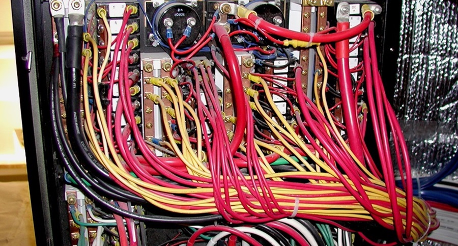
The back of a wiring panel can look pretty daunting, but remember, you're only troubleshooting one circuit at a time.
For people just getting into boating, or for those who have been boating for a while but have managed to avoid the electrical side of things, the 12-volt DC (direct current) systems aboard most boats don’t have to be daunting. Electricity operates in predictable ways, even if it is invisible, and learning to work with it will make you happier and safer on the water. Let’s get started with some marine DC basics so that you can do some troubleshooting and make safe, reliable electrical installations on your own.
12-Volt Basics:
- Definitions: Volts, Amps, Watts, Ohms
- Basic Circuit Design
- Marine Batteries and Charging Systems
- Power Distribution
- Wires and terminals
- Selecting a Multimeter
The Major Players – Volts, Amps, Watts, and Ohms
One of the primary players in this game, voltage, or volts, can be thought of as the pressure or force available in an electrical circuit. But another definition of voltage describes it as a difference of potential from one point in the circuit to another. As I’ve gained more experience working with electrical systems over the years I’ve found myself embracing the ‘potential difference’ definition. The reason is simple: If there is no potential difference in the circuit, there can be no current flow. Electrical current, or current flow, is sometimes described as the ‘flow of electrons’ within a circuit. The words that apply to this flow are ampere, amps, and amperage. Amperes express the volume or number of electrons that pass a given point in a circuit in one second. Now, it’s worth considering the definition of circuit, too. We can think of it as a route with a starting and finishing point at the same place, like a racecourse with the same starting and finishing line. In the case of electricity on a boat, think of that circuit leaving and returning to the source of power, which could be a battery or the shore-power pedestal on the dock. Along the way, electrical gear on the boat will take power from the current flow in that circuit and use it to show us electronic charts, pump the bilge, and perform all sorts of other chores for us. As for the term power, it’s best described as “the rate of doing work or expending energy,” and it’s measured in watts. Almost every piece of electrical equipment we use on a boat will have a label (or a manual) that tells us its demand for amperage, its output in watts, or both. Ampere-hours ( abbreviated Ah) is the term used to relate the capacity of a battery to the electrical demands we’re making on it, or planning to make on it. It means the current in amperes multiplied by the amount of time it flows. All batteries are rated for a certain number of ampere-hours to give us a general idea of how long they’ll provide power. Assuming a full charge but no connection to a charging source, a battery rated for 90 amp-hours would theoretically be able to give you 90 amps for one hour, 45 amps for two hours, one amp for 90 hours, and so on. In reality, especially at high discharge rates, batteries don’t perform anywhere near their ratings, and you would use only a portion of that capacity before the battery should be charged again. Even people who are math-averse will appreciate the simplicity of the equations that allow us to weigh demand against capacity:
- Volts x Amps = Watts (example: 12 volts x 6 amps = 72 watts)
- Watts / Volts = Amps (example: 300 watts / 12 volts = 25 amps)
- Amps x Time = Ah (example: 2.5 amps x 5 hours = 12.5 Ah)
The final key player in all of this is the ohm, a measure of resistance to the flow of electrons from one point in a circuit to another. We can think of the ohm as the bad guy in this scenario, because resistance is something we usually try to reduce or minimize in a circuit (unless we need an electrical stove coil or an incandescent bulb, which use resistance to create heat and light).
Figure 1, which comes from one my early articles discussing basic electricity, illustrates what happens when volts, amps, and ohms play together. The ohm character – the villain – is making it tough for the volt guy to push the amp guy along the circuit. You can see intuitively what has to happen. For example, let’s say voltage stays a constant at 12 volts. If resistance (ohms) increases, what has to happen to amperage? It will always decrease. If an appliance is engineered to operate at a certain amperage (and they all are) then the performance of the appliance will be compromised. This can and often does equate to a bilge pump or blower fan not spinning as rapidly as designed, essentially creating a potentially dangerous situation.

Figure 1. The Ohms character is restricting the ability of Volts to push Amps along a circuit.
Looking at another example, suppose the voltage remains constant at 12 volts and the resistance is somehow lowered, what can happen to amperage? Take the most extreme case -- a short circuit to ground, where a wire has chafed through its insulator and is now touching your engine block or other electrical ground point in your system. The load or resistance has been essentially eliminated. Applying Ohm’s Law will give you an effective ohm value of zero. Amperage will skyrocket as the source of power tries to discharge itself through the power feed wire in question. The hope here is that an over-current protection device -- a fuse or circuit breaker -- will trip and open up the circuit, shutting down power before a major melt-down occurs.
So, knowing those three basics -- that wattage equals amps times volts, that by dividing wattage by voltage we can calculate the operating amperage, and that resistance needs to be minimized -- we have the understanding to begin to take charge of our marine 12-volt systems. For example, we can determine the rating for a fuse or circuit breaker, and we can select the proper wire size to supply a device without inadvertently holding back any of the amperage the device needs.
Basic Circuit Design
Now that you know who the key players in this game are, let’s take a look at how we can keep them from ever becoming visible to the naked eye. Essentially, as complicated as things may look on your boat, there are only two circuit designs that typically get employed -- the series circuit and the parallel circuit. Both of these circuit types have the same needs, it’s just that their inherent characteristics dictate that the series circuit only be employed when supplying electrical current to one device or load.
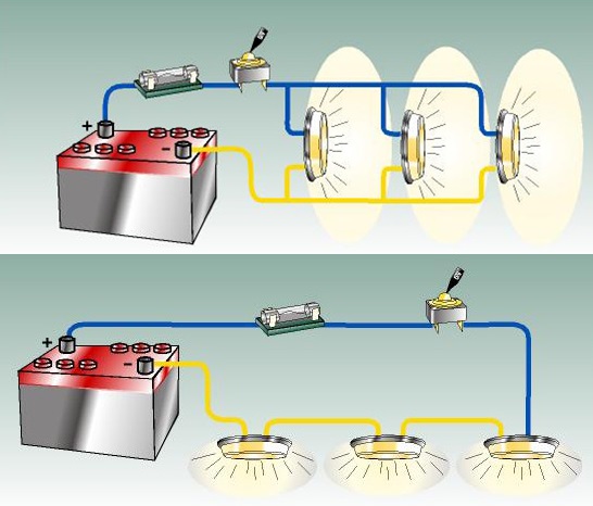
Figure 2. A parallel circuit (top) and a series circuit (bottom) are used for different jobs on boats. The wiring of individual devices will usually be in parallel circuits, with fuses or circuit-breakers available at an electrical panel.
Parallel circuits are what we typically see when we study the backside of most on board DC electrical distribution panels. Figure 2 illustrates what these two circuit configurations look like when drawn out. The important thing to remember here is that all electrical circuits on boats have the same needs. They are:
- A source of power, in this case a battery or multiple batteries.
- Overcurrent protection, a fuse or circuit breaker. The only exception to this rule is for engine starter motor circuits, although some builders are now installing breakers in those circuits as well.
- A switch, which is often integral with the circuit breaker at the DC panel board.
- Conductors to distribute the current. This includes wiring as well as things like relays, bus bars, and power distribution points -- at the back of a primary battery switch, for example.
- A load, or appliance – the reason we are paying attention to this circuit in the first place.
- A return path to ground at the source of power, typically the DC negative bus at the DC panel board.
Marine Batteries and Charging Systems
Marine batteries have evolved dramatically over the last 10 or so years, and there’s much to know about them. For newcomers to marine electricity, though, what you really need to be aware of is the importance of matching your boat’s charging system(s) to the needs of your battery(s). Doing this will not only make sure things are safe (over-charging batteries lets them emit explosive hydrogen gas), but will also ensure that you get the maximum life expectancy from your battery investment. So, regardless of the battery type or chemistry you choose, the best advice here is to study the re-charging requirements found on a specification sheet specific to the exact battery(s) on your boat and make sure your engine-driven alternator and shore-power-supplied battery charger are delivering no more than the maximum voltages prescribed by the battery maker.
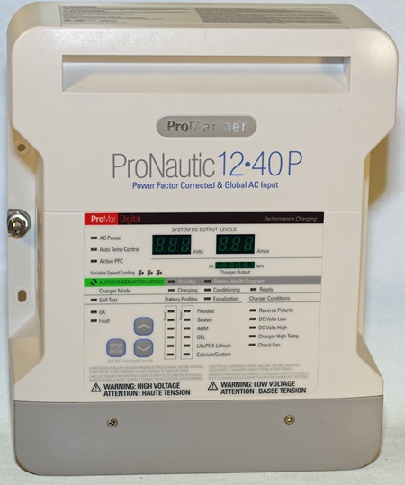
Figure 3. A modern multi-phase battery charger needs to be calibrated to the system it's working with.
In the case of multi-phase chargers, the voltages and battery type selector switches all need to be set according to the directions that come with units. As for the engine alternators, most have internal voltage regulators with fixed settings, so just make sure the maximum output doesn’t exceed your battery manufacturer’s specifications. Typically gel-cell type batteries are the most sensitive here. In Figure 3 you can see some of the typical adjustment settings on a modern multi-phase battery charger.
Power Distribution
On most boats, DC power is distributed via some sort of master switch panel or panels. These panels range simple four- or five-switch setups to complex boards with 20 or 30 circuits supplied. If you want to develop your skillset as an effective electrical troubleshooter, the secret is to focus only on the troubling circuit in question. Think back to the requirements for a properly functioning circuit and focus on the elements needed by the circuit to work normally. If one or more of those circuit needs are not being met, a problem will exist. Your task is to figure out which of those needs are not up to snuff and make the appropriate repair.
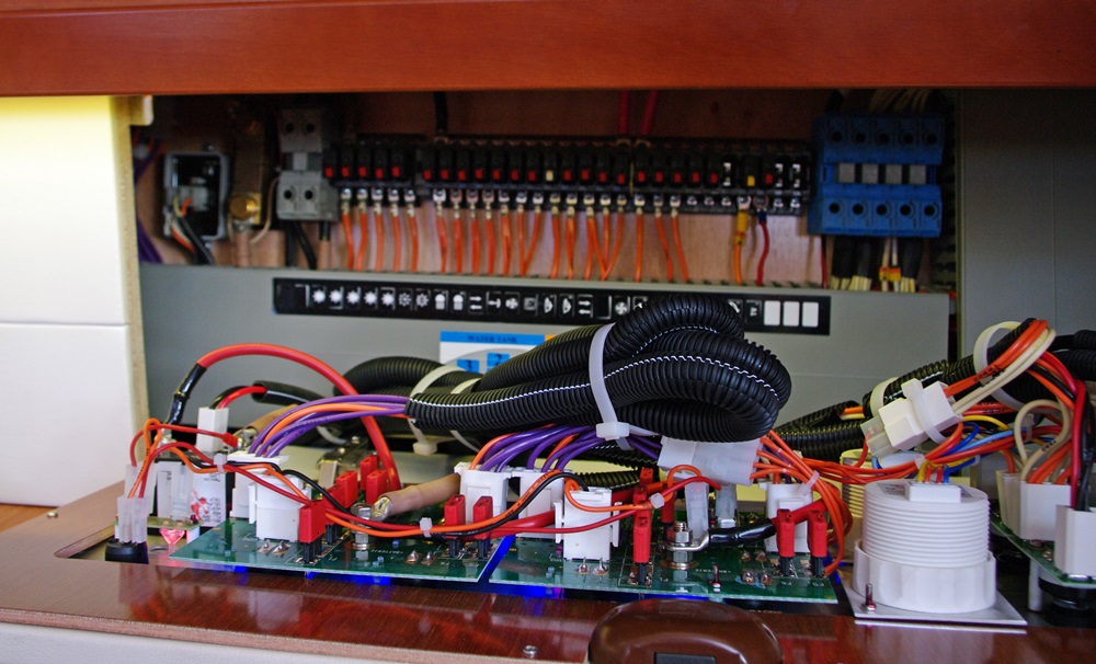
Figure 4. The back side of a panel will reveal lots of wire terminals and circuit breakers or fuses, but you don't have to look at everything at once. Remember that each breaker is part of its own circuit.
This is a really important concept to accept because a look at the back side of a typical panel board is sure to be intimidating initially, due to the large number of wires, bus bars, and termination points you’re looking at. Focus on the circuit breaker or fuse and associated wires that are supplying the circuit you’re have trouble with. Figure 4 shows the back side of a typical panel board supplying DC circuits on an average boat. This particular boatbuilder opted for the use of thermal mini-breakers, popular on European boats for a few years now. These are about the same size as the ATO or ATC type fuses you may see in your car. They are amperage-rated like fuses, but unlike fuses they’re resettable. Each of those breakers will be a part of its own separate circuit. Sometimes a tripped circuit breaker can be the only reason the circuit isn’t functioning, if it’s tripped by accident or a one-time event -- but usually there’s an underlying cause for the breaker to trip that will need to be found and repaired.
Wires and terminals
Wiring and terminations are the means to get power delivered to the various bits of electrical equipment we install on our boats. As a matter of fact, those of us with many years of experience in these matters will always tell you that the vast majority of problems with electrical systems occur at termination points. So, with that said, matching terminal size to wire gauge (wire diameter) is important. Also, using the proper tools to strip insulation and then crimp on the terminal is imperative to minimize potential problems. The tool kit I use for these tasks is shown in Figure 5.
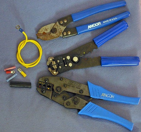
Figure 5. Good-quality tools for stripping wire and crimping connections will make a big difference in the security and longevity of wire terminals.
Aside from gauge size, wire type is also an important consideration. There’s a difference between SAE automotive wire and marine-grade AWG-sized wire. For the same gauge size, let’s say 10 GA, the difference in actual copper will be significant. Figure 6 shows the difference quite clearly. On the left side of the photo you see automotive SAE 10 GA. On the right is 10 AWG boat cable. The boat cable is also tinned, which makes it more corrosion-resistant in the marine environment.
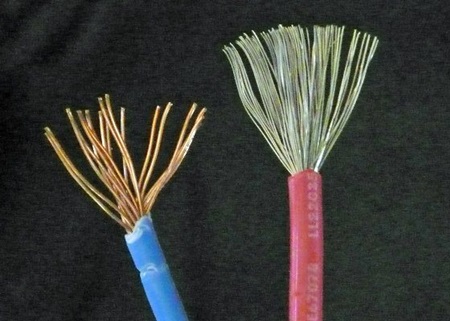
Figure 6. The marine-grade wire on the right has a better supply of copper, and the wire is tinned to prevent corrosion.
Some builders and do-it-yourselfers use untinned wire that provides acceptable service life with their systems, so don’t fret that too much – but remember that the greater copper content and protective tinning of marine-grade wire is better in the long run.
Selecting a Multimeter
A multimeter will be your main diagnostic tool when it comes to troubleshooting your DC system. This is definitely an area where spending a little bit more money up front will pay off in the long run. My favorite multimeter for beginning electricians is the Blue Sea model 8110. It measure volts, ohms, and amps in both AC and DC values, and offers a degree of sensitivity that meets the needs of the average, and even some not-so-average troubleshooting situations. For a full explanation of how to use such a meter, my PowerBoater’s Guide book provides great detail and pictorial step-by-step instructions. The 8110 is shown in Fig.7.
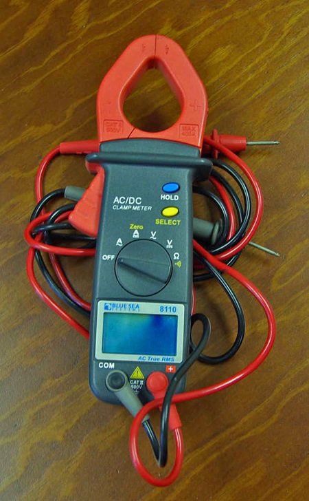
Figure 7. The Blue Sea 8110 is a good multimeter for novice marine electricians.
Knowing your way around the 12-volt electrical system on your boat will make you a better and safer boater. You might even become the go-to amateur when your friends on the dock are having trouble themselves. I hope this article will get you started on your way.
For more information on marine 12-volt basics, read Electrical Resistance on Boats: Keep That Voltage Drop in Check and All About Amperes in a Boat’s Electrical System.
Editor’s note: Ed Sherman is a leading authority on marine 12-volt systems and marine technical matters, and is a regular boats.com contributor. You can learn much more about DC systems from his two essential books on the subject: The 12-Volt Bible for Boats, 2ndEdition, and The PowerBoater’s Guide to Electrical Systems. Also visit Ed’s website --www.edsboattips.com – to read his advice and pet peeves on all sorts of marine systems and their installations. This article was originally published in October 2015 and was last updated in October 2021.